USB-C PD in a ThinkPad T440P

USB-C looking like “it came that way” in a T440P
These days most all new devices are using USB-C for power delivery and rumor is that the next iPhone will also sport USB-C. That got me thinking… why can’t my favorite laptop of all time… my trusty dual boot Win 10 / Mojave T440P be upgraded to USB-C for power. That would really bring the laptop to today’s standard and eliminate the reliance on the factory Lenovo power adapters. In addition, since we have several MacBook Pro’s, traveling with my wife becomes easier as a single USB-C charger would support us both. So, I went for it… did a little research… and did it. Below are the steps I took. As usual with all DIY guides, this is what worked for me and you should only do this if you understand the risks. You are on your own and anything you do to your laptop is at your own risk. I’m a tinkerer and not an expert in electronics, fire hazards, etc.
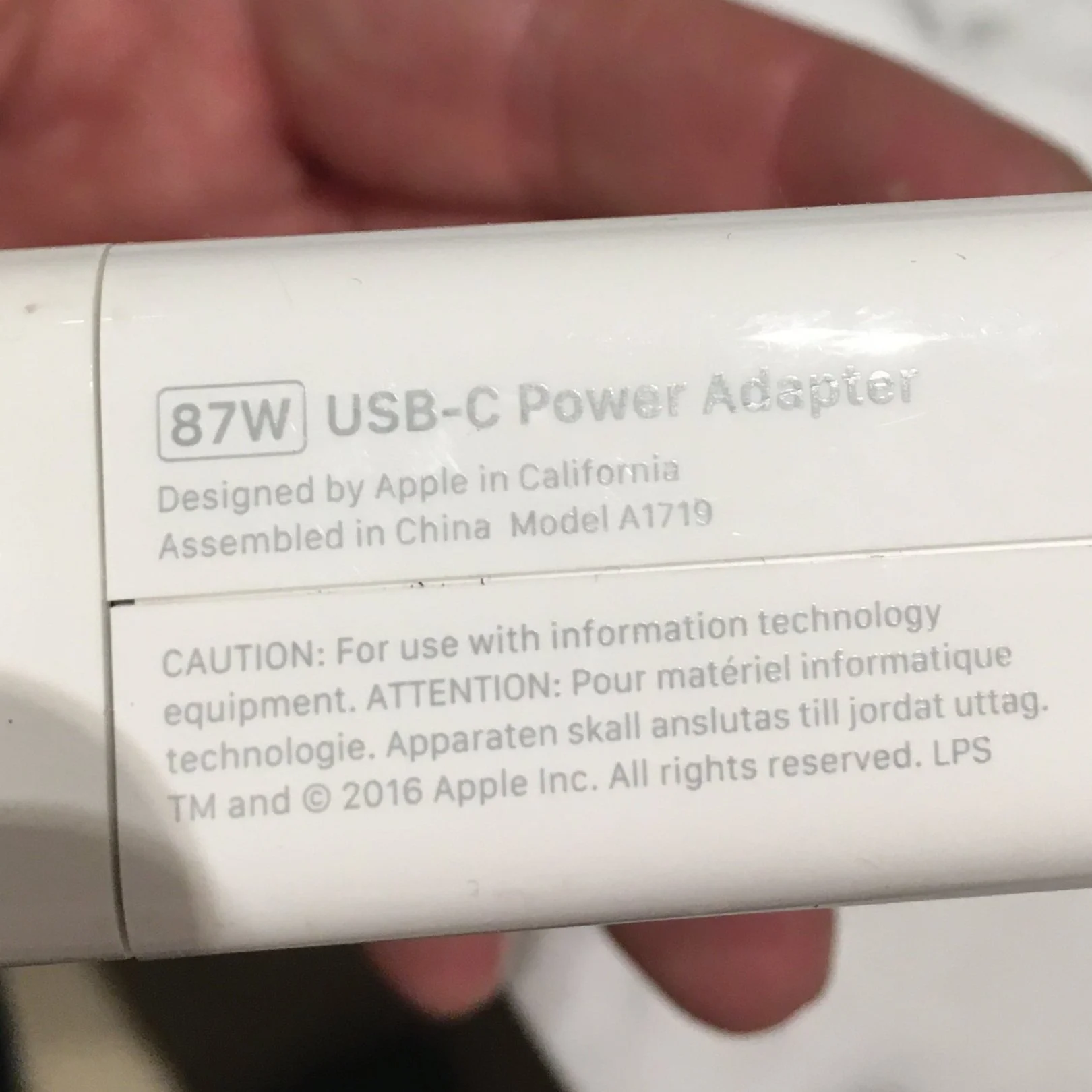
USB-C Power Delivery… What is it? Power Delivery (PD) is a specification for handling higher power and allows a range of devices to charge quickly over a USB connection. It operates by facilitating a conversation between two devices to negotiate a power contract so they can determine how much power can be pulled from the charger. Power Delivery starts at the 5V setting and is configurable up to 20V. Using a standard USB-C cable, it can handle up to 60W, and will go up to 100W using a designated EMCA cable. Luckily for us, our T440Ps are also charged by 20V, so I figured that it is possible to make this work. I purchased this PD from eBay.

Verify the Voltage. Next I verified the voltage of the factory power adapter and the USB-C PD using a multi meter. Both came out at 20V which was great. I did not have the solder anything on the PD that I purchased to change it from 5V to 20V. There are little solder pads on the back to force it into 5V or 20V. Mine was already set to 20V which saved me a step.

Factory power adapter putting out 20V. This is a 90W Lenovo power adapter.

USB-C PD also putting out 20V. This is connected to a factory Apple 87W USB-C charger from a MacBook.
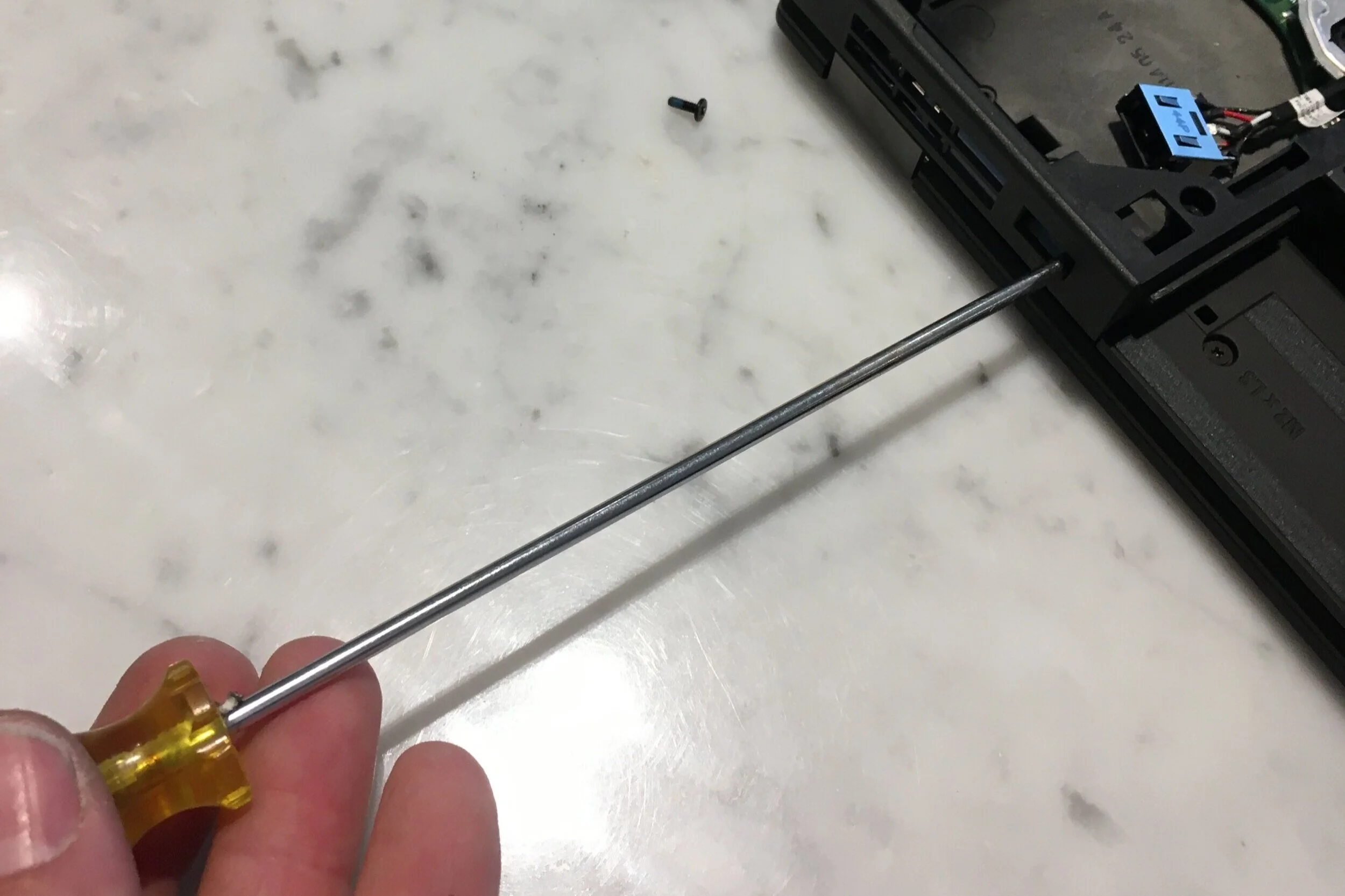
Remove the Plug. Now I had to figure out how to remove the plug from the laptop. First, remove the two screws on the bottom and slide off the bottom cover. If you are reading this, you have probably already tinkered with your T440P and you already know how to do this. Second, remove the CPU fan and set aside. Probably a good idea to clean the thermal paste off now since it will get everywhere. Third, I removed the two screws to the left and right of the plug to allow a little more flex in the plastic. Fourth, unplug the factory power plug from the mother board. Fifth… the hard part… we have to force the plug out. One of the stand offs is kind of in the way, but it is plastic so it flexes. I used a relatively thin flat blade screwdriver, placed it in the plug from the outside, and gently tapped on the left and right over and over again to un-seat the plug from the computer case. It is just pressed fit in there with two metal clips.
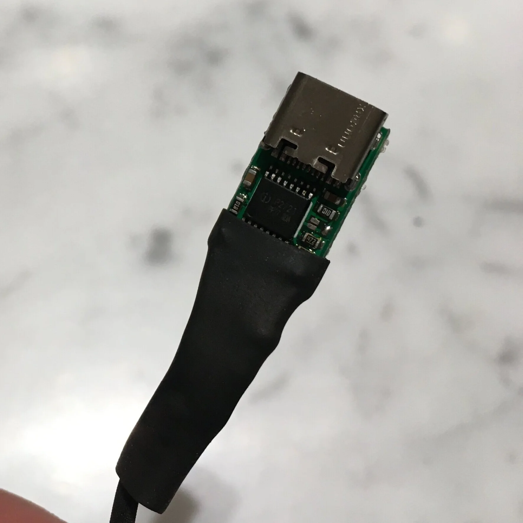
Time to Solder. The hard part is over. Now the fun part. Unsolder the five wires from the factory plug. Super easy to do. 2 Red, 2 Black and 1 white. No surprise here, but the 2 Red are Positive the 2 Black are Negative and the 1 White is SENSE. The White is the tricky one and we will get to that in a bit. Next solder the 2 Red to the positive solder pad on the USB-C PD and the 2 Black to the negative solder pad on the USB-C PD. Check your work by plugging in a USB-C power supply and making sure your volt meter shows 20V.

The White Wire. The White Wire is the SENSE wire. It tells the laptop what wattage power supply is connected to the computer. Normally, this is housed in the Lenovo charger and the white wire gets a signal from the Lenovo charger telling the wattage. In our case, we are using USB-C power and the sense wire is not present. So I was stuck. Without the white wire, the computer simply wont charge, turn on, anything. So I did some research and found this post which was super helpful in figuring out what was going on. In a nutshell, there is a resistor in the factory Lenovo charger end that connects the white wire to ground (the black wire). So we also have to place a resistor between the white wire and ground. No resistor = super low wattage and the computer will only turn on but not charge a battery or charge a battery when turned off but not both. I am guessing that no resistor (white wire connected directly to ground) must signal 35W or something low like that. According to the post I linked to, 550 Ohm = 90W, 1kOhm = 135W, and 1.9kOhm = 170W. Since the Apple charger is 87W, I wanted 550 Ohm, but I didn’t have any resistors. So, I stole a resistor off an educational toy my son had. In this case the closest resistor was 470 Ohm and it seems to work perfectly.

I stole a 470Ohm resistor from this educational toy.
Now, simply solder the resistor inline with the white wire and negative on the USB-C PD. Basically it joins the black wires.

I then used some heat shrink to clean up my work and protect the solder pads. In reality, the heat shrink was probably not necessary. I probably should have just used heat shrink around the white wire and resistor. You need the wire to be flexible to curve around the fan. Mine worked perfectly but the heat shrink stiffens up the wire assembly and it is a little harder to flex it around the fan.
Modify the Factory Plug. Time to bust out the Dremel and modify the factory plug. Basically, you just need to remove all the plastic from the inside making an empty rectangle. Takes less than minute.

Glue in the USB-C PD. Now you will be shocked as to how perfectly the PD fits into the factory housing. It is like it was begging for this mod. I used a drop of super glue and a hot glue gun. JB Weld would have been good too but a little more permanent.

Reinstall. Now we just reverse our steps and reinstall the plug. Just like before, that stand off is a little in the way. Just work it in at an angle and tap it in from inside the computer with a thick flat blade screw driver. Take your time and it will simply press fit in place. Make sure your glue is dry before you reinstall so that the USB-C plug stays nice and centered in the factory plastic case. Don’t plug the power connector to the motherboard yet. It is better to apply new thermal paste to the CPU and reinstall the fan. This way you can bend the power wires out of the way as you put the fan in. Lastly, connect the power wire to the motherboard, affix the bottom case with the two screws, and you are done!!!

This picture shows the power connected to the motherboard, but the fan isn’t in yet. It is better to put the fan in first so you can manipulate the wire around the fan. Then plug the wire to the motherboard last.
Finished Product. It simply looks like the computer came that way. So happy with the result and now I can charge with a USB-C charger, which are so much more common than a Lenovo charger. Totally convenient and a fun project on top of it all.